Legged robot research has been an active area of study since the late nineties. Let’s take a look at how we can generate walking trajectories for bipedal robots, using some of these ideas.
The Objective: Implement a quick and dirty way of generating walking trajectories
Constraints: Do it quickly. Minimize sophistication. Anything goes!
What this post will cover:
- Overview of the minimal set of ideas required to develop walking algorithms
- Computation of bipedal joint trajectories for a simple walking gait
What will not be covered:
- Details regarding any of the individual parts
- Execution of the computed trajectory
Code for the implementations in this post can be found here.
$\newcommand{\norm}[1]{\left\lVert#1\right\rVert}$ $\newcommand{\st}{\text{s.t.}}$ $\newcommand{\fcom}{f_{com}}$ $\newcommand{\gcom}{g_{com}}$ $\newcommand{\qkj}{q_{kj}}$
ZMP
Bipedal research has come a long way, with us being able to control robots in extremely agile, contact implicit ways (looking at you Boston Dynamics). But the algorithms in this space has roots in much simpler ideas. ZMP or zero moment point is one of the oldest and most popular ideas used in legged locomotion. Robots of the late 90’s and early 2000’s (P2, Asimo, etc) employed ZMP based methods for walking. In the spirit of this post, we quickly summarize the major ideas here, without going into any of the details.
The core idea here is that even for a bipedal system with complex dynamics, the dynamics of its center of mass (COM) is pretty simple. So we can come up with a relatively simple control law for the center of mass dynamics, which can then be tracked. The zero moment point (ZMP) is a point on the ground where the net horizontal moment of all the contact forces is zero. For a bipedal robot, as long as this point is inside the convex hull formed by the feet of the robot (that are in contact), the robot will not tip over (zero moment), and will hence be stable.
If we make an assumption that the height of the center of mass, of the robot, does not change, it simplifies things even further.
\begin{equation} \dot{z_{com}} = 0 \end{equation}
This also means that
\begin{equation} \ddot{z_{com}} = 0 \end{equation}
This is powerful, because this allows us to ignore the effects of feet-ground impact on the dynamics. Even though we have made a few concessions, the problem can now be solved kinematically without having to worry about any complicated dynamics.
The COM to ZMP relationship then turns out to be:
\begin{equation} \begin{aligned} \ddot{x_{com}} = \frac{g(x - x_{zmp})}{h}\\ \ddot{y_{com}} = \frac{g(y - y_{zmp})}{h} \end{aligned} \end{equation}
Where
\begin{equation} h = z - z_{zmp} = \text{constant} \end{equation}
The equations look similar to an inverted pendulum with linearized dynamics, which is why using ZMP in this way tends to be considered an LIP model, with the mass of the robot assumed to be concentrated at the center of mass.
This relationship is linear! (affine if strictly speaking). If the position of the ZMP is given, it also tells us how the dynamics of the COM will evolve.
Now the question is how do we use this?
Gait Trajectory Generation
A simple way of generating walking gaits using this principle is to do the following:
- First assume foot positions on the ground. We assume that we have a stance phase where we hold contact on both feet while also changing the COM, and a swing phase, where one foot swings forward to the next position. The stance and swing phases alternate between feet to form a walking gait
- As we require the ZMP to be within the convex hull of the feet contact polygon, we can make assumptions about the trajectory of the ZMP given the positions of the feet over time
- Given the ZMP trajectory, we can then use the COM dynamics equations to compute the trajectory of the COM
- And finally, we can kinematically solve for joint angles, that can track this COM trajectory
Foot Placement
We can use sophisticated methods to solve for dynamically feasible foot positions, but for the most part, we can just set up these positions heuristically. The only constraint is that they need to be feasible in terms of being able to track the COM while constraining the feet to these positions, but taking small incremental steps will work in most cases.
ZMP Trajectory Generation
We can just set the ZMP at any time to be the center of the convex polygon hull made by the feet currently in contact. This means that at the end of the stance phase, as we’re lifting the swing leg, the ZMP must now be within the convex hull of the single stance feet making contact.
COM Trajectory Generation
Solving for the COM can be trickier that it looks from the ZMP equations. We need to compute a COM trajectory such that the derivatives of the trajectory at every point satisfy the required relationship.
There are more recent methods that solves this problem using a closed form solution [1]. To comply with our initial objective and constraints, I used one of the earliest methods developed for solving this problem: COM generation using preview control. For details, see [2] and [3].
The end result is this:
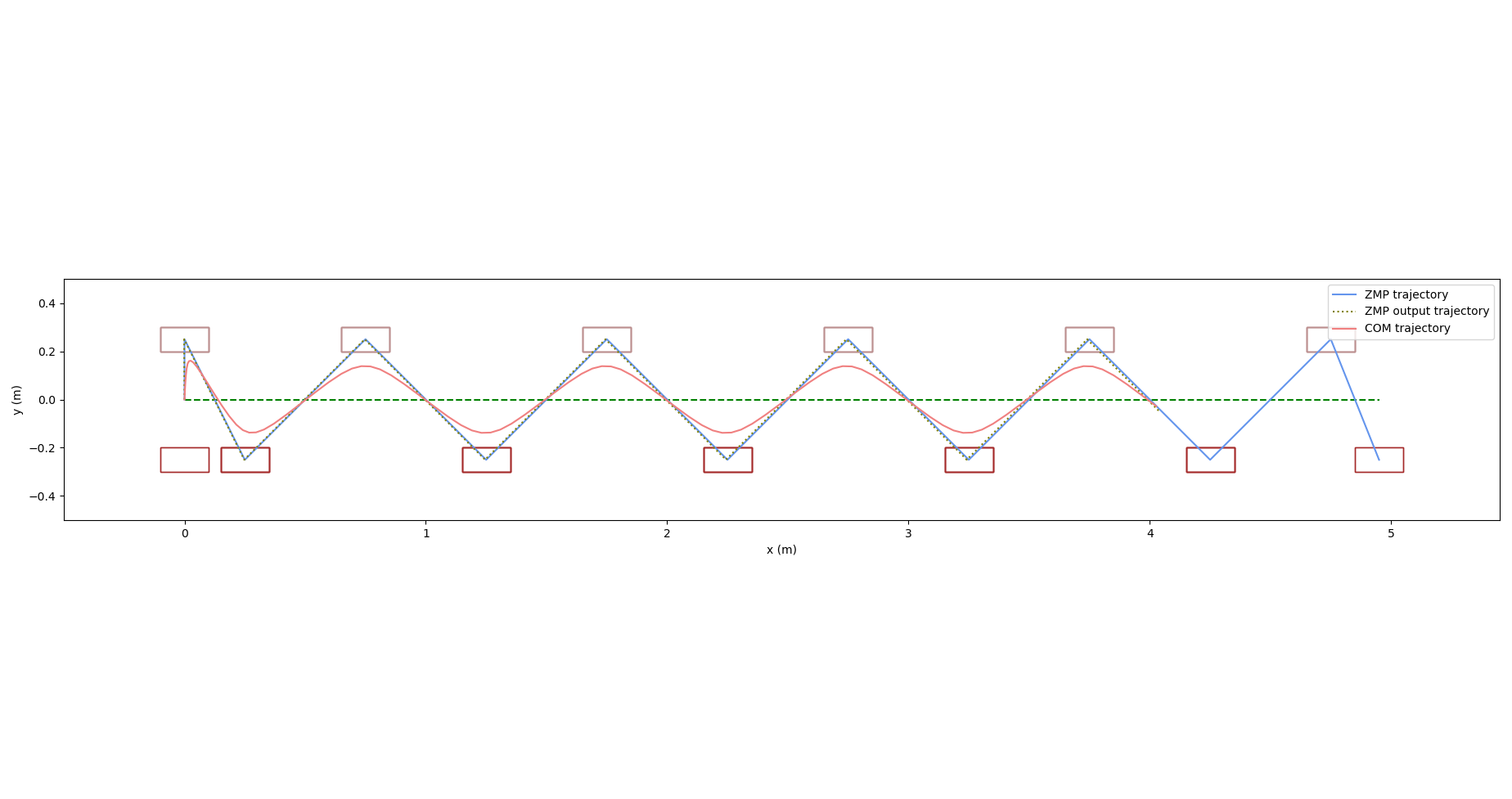
Here we can see the required path to track in green, along with positions of the feet (brown rectangles – light brown represents the left foot and dark brown represents the right). The blue trajectory represents the ZMP trajectory and we can see how it is always within the convex hull of the feet that are in contact. As we switch from swing to stance, we can see how the ZMP switches to be over the stance feet to maintain balance. The orange trajectory is the COM trajectory computed using the preview controller. The dotted line over the ZMP trajectory is the ZMP trajectory computed using the COM trajectory solution. A good solution of the ZMP equations will result in this re-computed ZMP trajectory being almost coincident with the original ZMP trajectory, which we can see is the case here.
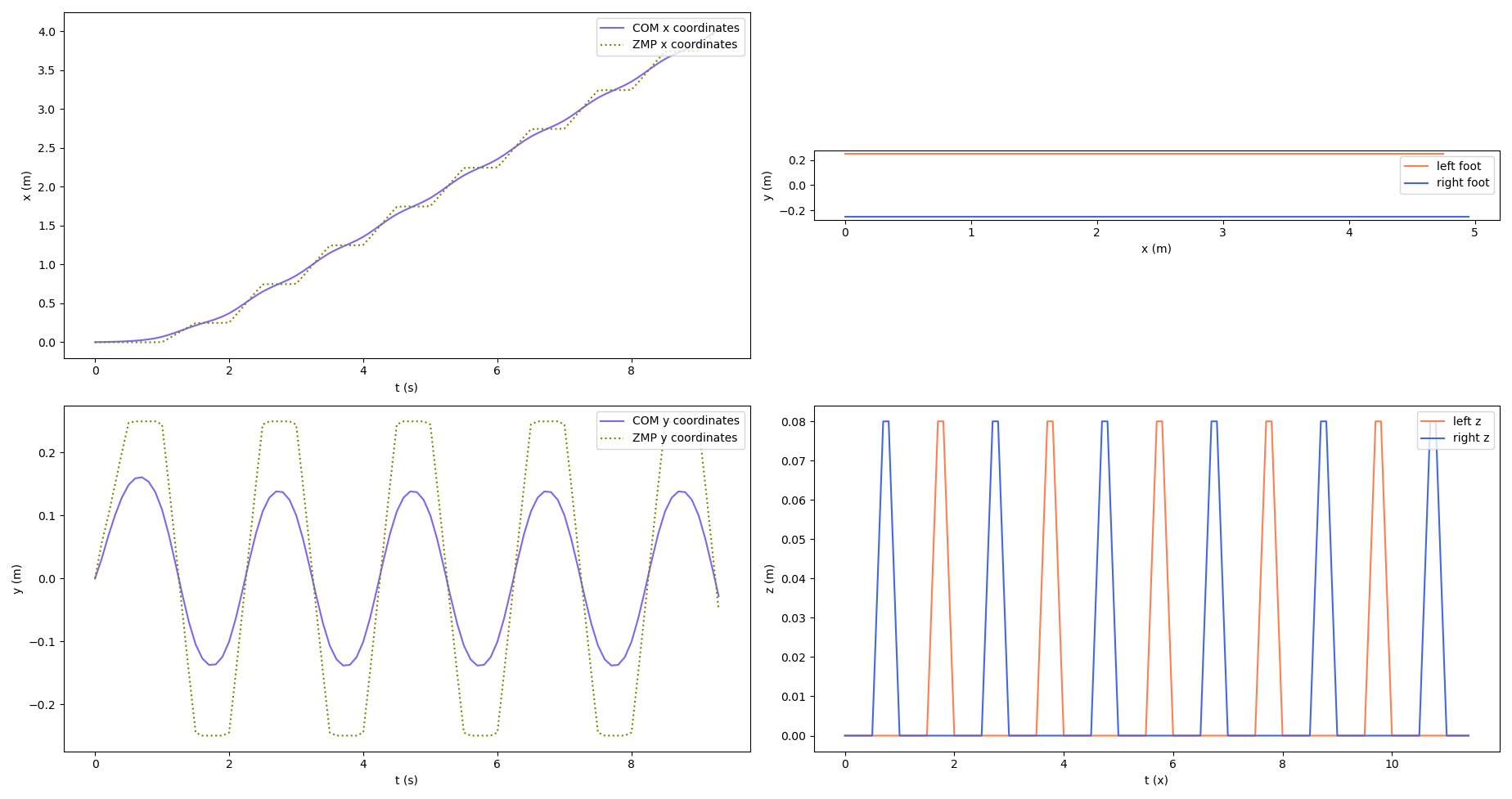
We can also plot the trajectories of each individual foot, in $x$, $y$ and $z$, along with the $x$ and $y$ components of the COM trajectory.
For the $z$ coordinates of the feet, we assume that each foot is lifted by a certain constant amount above the ground during the swing phase. Usually, the swing phase feet trajectories are represented by some sort of spline so that we get smooth motion, but my implementation here sets them as as linear piecewise trajectories as seen in the plots.
Joint Trajectory Generation
To wrap things up, we need to convert this COM trajectory into a trajectory of joint angles. For simple bipedal systems, we might be able to find approximate closed form solutions for the joint angles for the given center of mass, but for my test, I used Unitree’s H1 robot model, which has a total of 19 actuated joints!
We can use this to our advantage by formulating the problem as a non-linear optimization problem. Because of the high dexterity of the model, we can be reasonably confident that the optimizer will find good solutions even with a lot of constraints on the kinematics. We make the following considerations:
- We split the trajectory into alternating stance and swing phases for each leg. This keeps each optimization problem independent and simple. It has the disadvantage of being open loop and resulting in some inconsistencies, but we won’t get into that here
- We don’t solve for any of the upper body or arm joints and fix them to be zero (or whatever the initial configuration is)
- The COM is purely a kinematic function of the joint angles. Even though it is non-linear, it makes it easy to represent the COM constraint in the optimization problem.
For each phase from time $t_s$ to $t_e$, we divide the trajectory into a number of sample points (denoted $t_k$) and solve for the joint angles at each point, given the constraints. This is basically solving a series of IK problem for each phase and is similar to generating trajectories for manipulators. We have the following constraints at each sample point:
- The left and right feet at time $t_k$ when the joint angles are $q_k$ (Given by the forward kinematics $f_l(q_k)$ and $f_r(q_k)$) must be at positions $g_l(t_k)$ and $g_r(t_k)$ given by the left and right feet trajectories $g_l(t)$ and $g_r(t)$
- The COM (Given by the forward kinematics $\fcom(q_k)$) must be at $\gcom(t_k)$
- $\qkj$ for the joint indices $j$ corresponding to the upper body (Set $U$) must be 0
In order to generate smooth trajectories, we add a cost between the joint angles of successive sample points. This will help prevent the solver from finding solutions that switch rapidly, especially when multiple IK solutions are available for a given sample point.
The optimization problem looks something like:
\begin{equation} \begin{aligned} \min_{q_k} Q\sum_{k=0}^{K-1} \norm{q_{k + 1} - q_{k}}_2\\ \st \fcom(q_k) = \gcom(t_k)\\ f_l(q_k) = g_l(t_k)\\ f_r(q_k) = g_r(t_k)\\ \qkj = 0, \ j \in U \end{aligned} \end{equation}
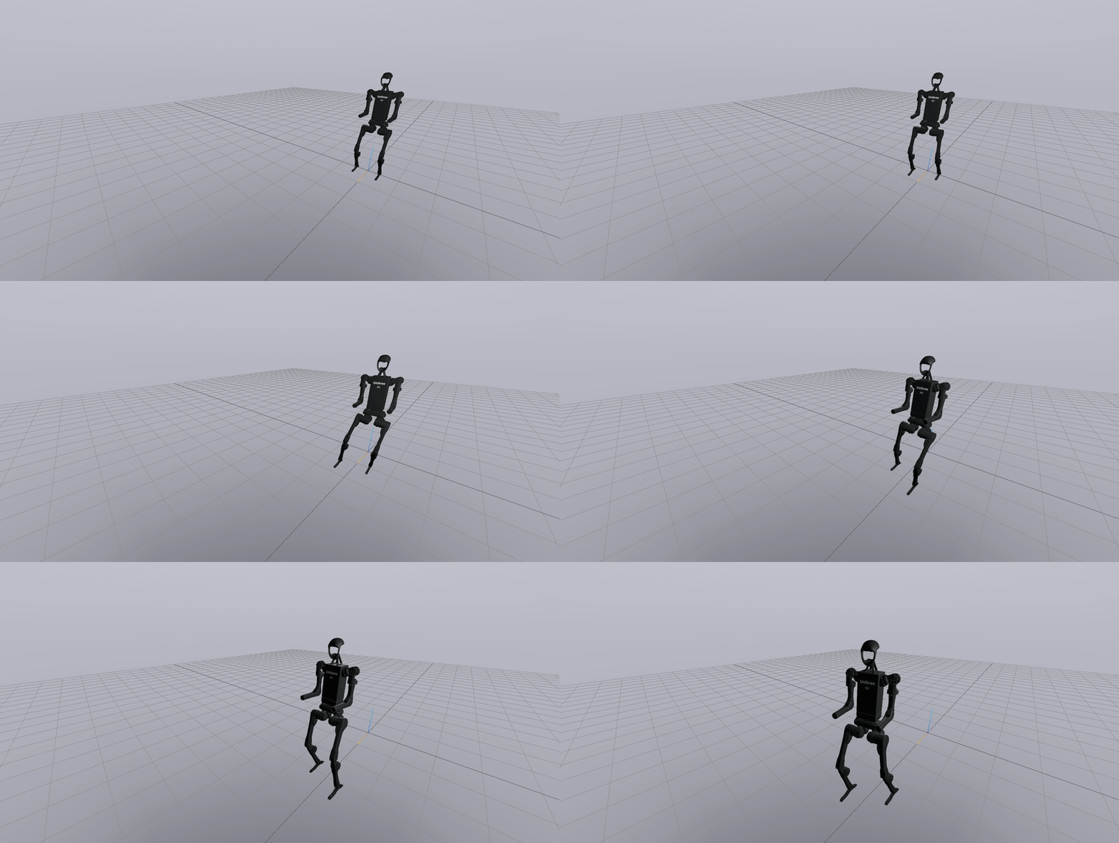
Solving this, will give us a series of joint angles $q_k$ corresponding to a single walking phase. We can accumulate these together and obtain a walking gait trajectory. This is what the end result looks like:
Final Remarks
Note that actually executing/tracking this trajectory requires more work. Open loop control here will almost never work, and the system will need to have a feedback controller running at a pretty high frequency that helps track the COM and stabilize the robot. Some methods also combine the COM generation and stabilization into a single controller and can allow for greater deviation and recovery.
On a real robot, it is also common to have sensor modules to help compute estimated instantaneous positions of the ZMP, either by using pressure sensors on the feet or joint torque sensors.
All in all, even though we haven’t executed these gaits, just computing the trajectories can teach us a lot about the nuances of the problem and help us appreciate the beauty of bipedal robots.
References
- Tedrake, R., Kuindersma, S., Deits, R., & Miura, K. (2015, November). A closed-form solution for real-time ZMP gait generation and feedback stabilization. In 2015 IEEE-RAS 15th International Conference on Humanoid Robots (Humanoids) (pp. 936-940). IEEE. [Link]
- Kajita, S., Kanehiro, F., Kaneko, K., Fujiwara, K., Harada, K., Yokoi, K., & Hirukawa, H. (2003, September). Biped walking pattern generation by using preview control of zero-moment point. In 2003 IEEE international conference on robotics and automation (Cat. No. 03CH37422) (Vol. 2, pp. 1620-1626). IEEE. [Link]
- Katayama, T., Ohki, T., Inoue, T., & Kato, T. (1985). Design of an optimal controller for a discrete-time system subject to previewable demand. International Journal of Control, 41(3), 677-699. [Link]


